MMDVM Digital Trunk Board — STM32-DVM(405 RPT) GPIO/USB Repeater/Hotspot

The MMDVM Digital Trunk Board (STM32-DVM 405 RPT) is a GPIO/USB-based repeater/hotspot board that connects to your Raspberry Pi (or compatible SBC) via the GPIO serial interface (UART) or USB. It runs at 460800 baud and supports both digital and analog FM modes.
Only one model available: STM32-DVM(405 RPT) — 460800 baud.
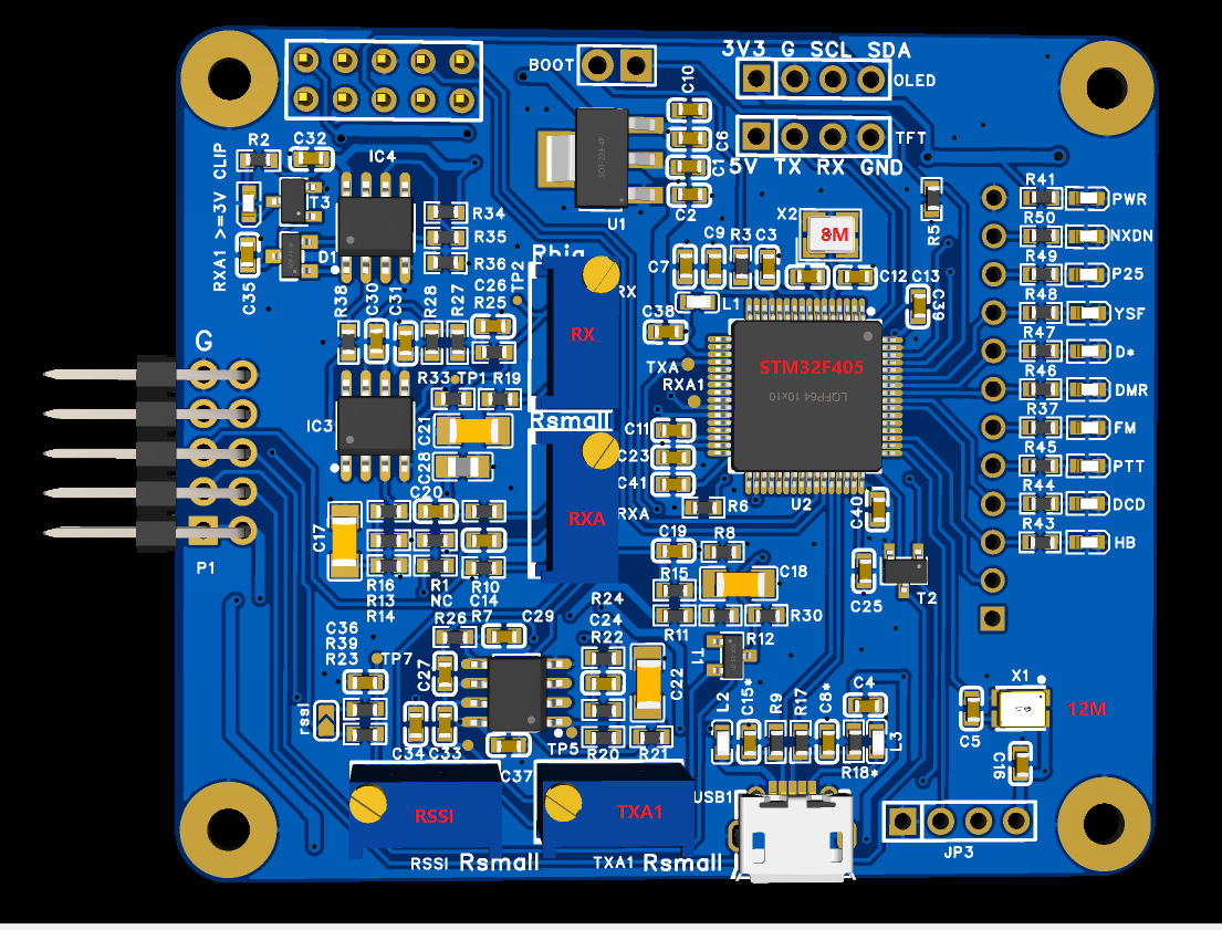 STM32-DVM(405 RPT) — front view
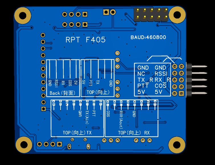 STM32-DVM(405 RPT) — back view
Supported Modes
- D-Star
- DMR
- Yaesu System Fusion
- P25 Phase I
- NXDN 4800
- POCSAG (paging)
- FM (460800 baud rate)
Key Specifications
- Model: STM32-DVM(405 RPT)
- Baud rate: 460800
- Interface: GPIO serial (UART) or USB (PL2303)
- Modes supported: DMR, YSF (C4FM), P25, NXDN, DSTAR, POCSAG, FM
- DMR timeslots: Dual-slot — acts as a mini digital voice repeater
- Frequency range: VHF/UHF (depends on your external radio)
- TCXO: High-quality ECS TCXO for stable, low-BER operation
- Display: Support 0.96 oled or 1.3inch (VCC GND SCL SDA)
What's in the Box
| Item | Description |
|---|---|
| PCB board | STM32-DVM(405 RPT) fully soldered and ready to use |
| 2x5 2.54 pinhead (Moto radio) | Connects board to radio |
| 2× 8pin Moto female headers | Included — gift for connecting to Motorola radios |
Connector Images
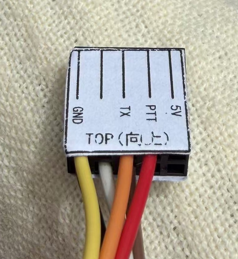 2x5 pin header — top view
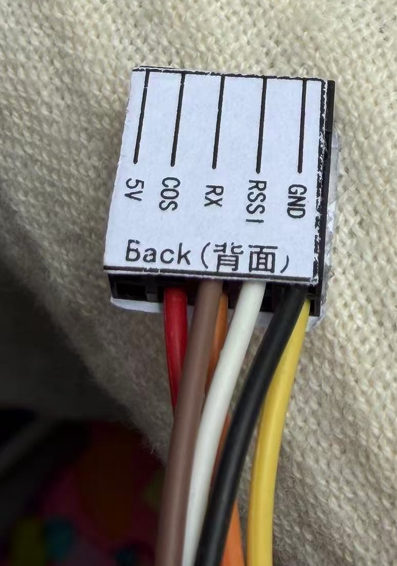 2x5 pin header — back view
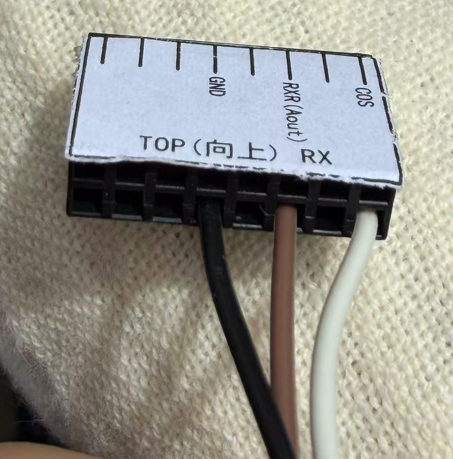 RX connector — top view
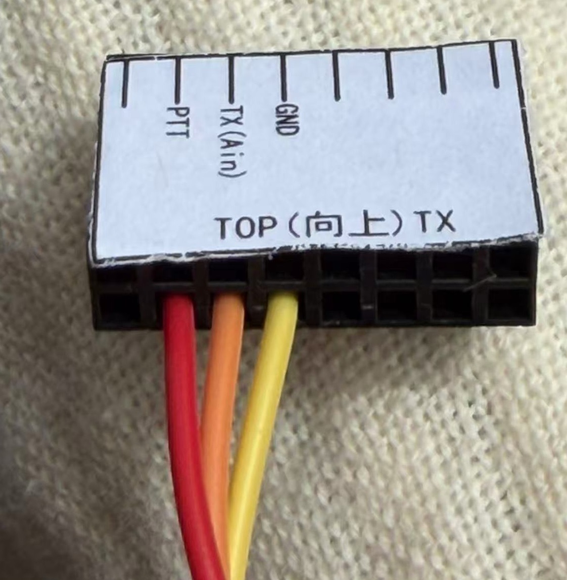 TX connector — top view
Compatible Hosts
Connects via GPIO serial (UART) to:
- Raspberry Pi: 3B, 3B+, Pi Zero, 4, 5
- FriendlyElec: NanoPi NEO
- Xunlong: Orange Pi
The serial port on Raspberry Pi is /dev/ttyAMA0 (or /dev/ttyS0 on some
models, depending on configuration).
Enabling UART0 on Raspberry Pi 5
If you're using the official Raspberry Pi OS on a Pi 5, UART0 (GPIO 14/15) is disabled by default. Enable it as follows:
-
Flash the SD card using Raspberry Pi Imager with the official OS.
-
Open the boot partition on the SD card — it mounts as
booton your desktop, or/boot/firmware/on the Pi itself. -
Edit
config.txt— append the following lines at the end:enable_uart=1dtoverlay=uart0=on -
Save, eject and reboot the Pi.
-
Verify — check that the serial device appears:
pi@raspberrypi:~ $ ls /dev/ttyA*/dev/ttyAMA0 /dev/ttyAMA10
If you see /dev/ttyAMA0, UART0 is active and ready for your MMDVM board.
USB Connection
The board can also be connected over USB (via the onboard PL2303/serial chip). It will appear as:
| Platform | Device |
|---|---|
| Linux (ARM) | /dev/ttyACM0 |
| Windows | COMxx (check Device Manager) |
⚠️ Only one interface should be configured at a time — either GPIO UART or USB serial, not both simultaneously.
FM Mode Details
Potentiometer Adjustments
The board has several potentiometers for tuning analog FM audio:
| Pot | Adjustment | Direction |
|---|---|---|
| RX | Volume increases | Clockwise |
| RXA | Volume decreases | Clockwise |
| TXA1 | Volume decreases | Clockwise |
DMR testing note: When testing DMR mode, TXA1 needs to be turned down (clockwise) so that your radio can properly decode the signal.
CLIP LED Behavior
In FM mode, the CLIP LED indicates:
| State | LED |
|---|---|
| Standby (no signal) | Red (lit) |
| Receiving FM signal | Off |
| DCD active (CTCSS matched, default 88.5 Hz) | Lit |
To enter FM mode, connect via serial (USB) and send the FM mode command. When CTCSS is matched (default 88.5 Hz), DCD will illuminate.
Configuration
[Modem] Section
[Modem]
Protocol=uart
# The port and speed used for a UART connection
# GPIO serial on Raspberry Pi:
UARTPort=/dev/ttyAMA0
# USB on ARM/Linux:
#UARTPort=/dev/ttyACM0
# USB on Windows:
#UARTPort=\\.\COM13
TXInvert=0
# For GM950x:
RXInvert=1
FMTXLevel=50
[FM] Section
[FM]
CTCSSFrequency=88.5
CTCSSThreshold=90

# AccessMode values:
#   0 - Carrier access with COS
#   1 - CTCSS only access without COS
#   2 - CTCSS only access with COS
#   3 - CTCSS only access with COS to start, then carrier access with COS
AccessMode=1
[FM Network] Section
[FM Network]
LocalAddress=0.0.0.0
LocalPort=3810
GatewayAddress=127.0.0.1
GatewayPort=32000
Duplex / Simplex Switching
Switch between repeater (duplex) mode and hotspot (simplex) mode by changing the RX/TX board line order — no firmware reflash needed.
Use Cases
1. High-Powered Hotspot
Connect it to a mobile radio (e.g., Motorola CDM series) and you've got a hotspot that covers your neighborhood instead of just your living room.
2. Full Digital Repeater
With two radios and a duplexer, the board's dual-slot DMR capability lets it function as a proper mini digital repeater.
3. Portable / Field Day Setup
Since it connects via GPIO or USB, it's easy to pack for field operations, emergency communications, or events with a Raspberry Pi or laptop.
4. BlueDV Integration
With an added serial module, the board can interface with BlueDV for cross-mode digital voice bridging.
Getting Started
- Connect the board to your Raspberry Pi GPIO header (or via USB)
- Install MMDVMHost (WPSD or Pi-Star)
- Configure the serial port in
/etc/mmdvmhost:UARTPort=/dev/ttyAMA0 # GPIO# UARTPort=/dev/ttyACM0 # USB on ARM/Linux - Set baud rate to
460800 - Set your mode (simplex or duplex) via the TX/RX wiring
- Configure FM if using analog mode — set CTCSS frequency and access mode
For GPIO connection, make sure the serial port is enabled on your Raspberry Pi
(enable_uart=1 in /boot/config.txt).
Product reference: alexnld.com